Difference between revisions of "Lindenis V853"
(→OS) |
(→OS) |
||
| Line 260: | Line 260: | ||
Kernel & Driver layer is the standard implementation of the Linux Kernel. And the Tina SDK for V853 is based on Linux-4.9 kernel. | Kernel & Driver layer is the standard implementation of the Linux Kernel. And the Tina SDK for V853 is based on Linux-4.9 kernel. | ||
| − | + | <br><br><br><br><br><br><br> | |
== Reference Documents == | == Reference Documents == | ||
Revision as of 11:45, 10 January 2023
Contents
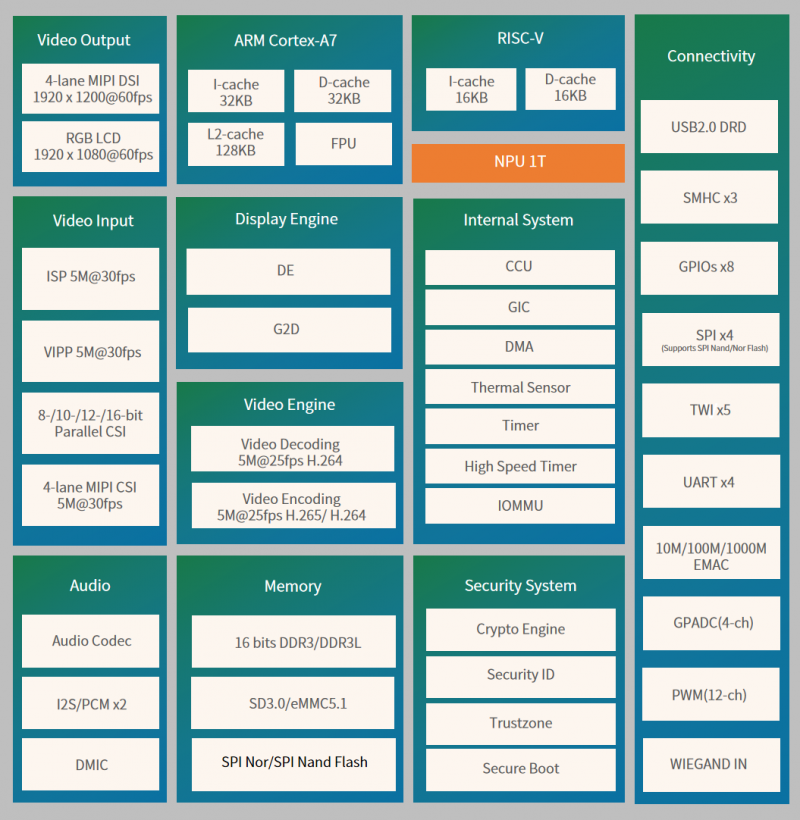
V853 Key Features
CPU
- Cortex-A7@1.2 GHz CPU core, supporting 32 KB I-cache, 32 KB D-cache, and 128 KB L2 cache
- Neon acceleration, integrated FPU
- RISC-V@600 MHz core, supporting 16 KB I-cache and 16 KB D-cache
NPU
- Maximum performance up to 1 Tops
- Embedded 128KB internal buffer
- Supports deep learning frameworks: TensorFlow, Caffe, Tflite, Pytorch, Onnx NN, and so on
Video Input
- ISP
- Maximum performance of 5M@30fps and maximum resolution of 3072x1772
- Adjustable 3A functions (AE, AWB, and AF), and 3A parameters are adjustable
- Supports ISP tuning tools for the PC
- VIPP
- Four VIPP YUV422 or YUV420 outputs
- Maximum performance of 5M@30fps and maximum resolution of 3072 x 1772
- 8-/10-/12-/16-bit parallel Camera Sensor Interface
- Supports digital camera(DC),BT.601,BT.656,BT.1120 protocol
- Maximum video capture resolution up to 5M@30fps
- 1*4-lane MIPI-CSI interface
- Supports DOL WDR mode and splitting into 2*2-lane MIPI-CSI
- Supports 4-ch VC de-interleaver function
- Maximum video capture resolution up to 5M@30fps
Video Engine
- Video encoder
- H.264/H.265 encoding up to 4K@15fps or 5M@25fps
- JPEG encoding up to 1080p@60fps
- Video decoder
- Supports H.264 BP/MP/HP,JPEG
- Real-time multiple streams H.264 encoding capability: 5M@25fps
- JPEG snapshot performance of 1080p@60fps independently
Display Engine
- Allwinher SmartColor post processing for an excellent display experience
- Supports 2 video channels and 1 UI channel
- Supports G2D hardware accelerator including rotate, mixer, scaler functions
Display Output
- RGB LCD output interface up to 1920 1080@60fps
- 1*4-lane MIPI-DSI interface up to 1920x1200@60fps
Audio
- 1 DAC and 2 ADCs
- Analog audio interfaces: MICIN1P/N,MICIN2P/N,LINEOUTP/N
- Digital audio interfaces:12S/PCM X2,DMIC
Security System
- AES, DES,3DES encryption and decryption algorithms
- RSA/ECC signature verification algorithm
- MD5/SHA and HMAC tamper proofing
- PRNG/TRNG hardware random number generator
- Integrated 2 Kbits OTP storage space
Connectivity
- USB2.0 DRD
- SDIO 3.0
- WIEGAND
- SPI x 4
- UART x 4
- TWI x 5
- PWM(12 Channels)
- GPADC(4 Channels)
- 10/100/1000M EMAC with RMIland RGMII interfaces
Package
- LFBGA318, 12mm x 12mm body size, 05mm ball pitch
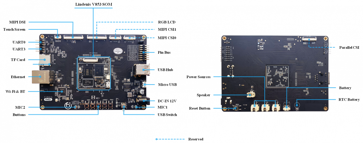
Lindenis V853 AI EVB
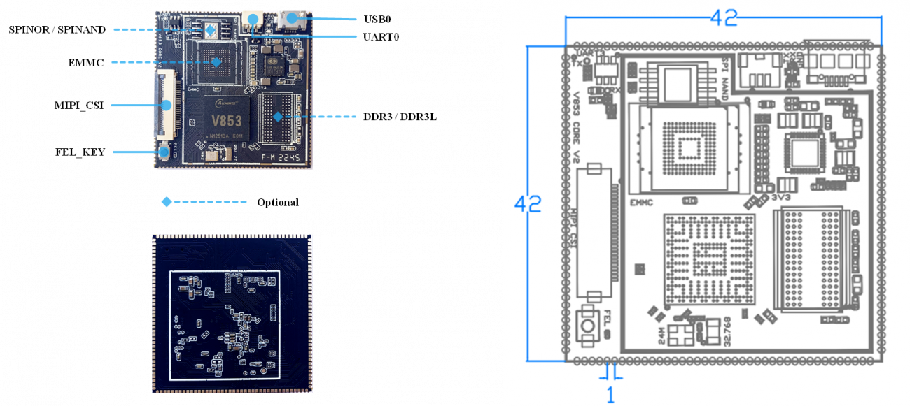
Lindenis V853 AI SOM
Lindenis V853 AI DevKit
Hardware Documents
Schematic
PCB Place Map
Dimensions
Datasheet
- If you want to get the Datasheet of V853, please send an e-mail to services@lindeni.com .
SDK
Overview
Features
- Linux kernel 4.9 (official version)
- U-Boot-2018
- ARM GCC based cross toolchain
- Integrated build system
Layout
├── build
├── config
├── Config.in -> config/top_config.in
├── device
├── dl
├── docs
├── external
├── lichee
├── Makefile -> build/top_main.mk
├── package
├── prebuilt
├── rules.mk -> build/rules.mk
├── scripts
├── target
├── toolchain
└── tools
Download and Build
Prebuilt Image
For fast begin, you can download the [prebuilt image here.
[ 国内开发者请在此下载]提取码:
System requirements
Listed below are the recommended requirements for downloading and building the SDK:
- CPU: x86_64 or better family processor
- Memory: 8GB or higher
- Disk: 20GB free hard disk space, if you build it in a Virtual machine, I recommand you allocate a 30G virtual hard disk.
- The Whole SDK is about 15G.
- OS: Ubuntu 14.04 (tested) or higher
- Network: internet connection
Lazy Start
Linux host setup
Ubuntu 14.04
HINT: later version should also work.
Install prerequisites
$ sudo apt-get update
$ sudo apt-get install build-essential libncurses5-dev zlib1g-dev gawk git git-core ccache gettext libssl-dev xsltproc gperf subversion
$ sudo dpkg --add-architecture i386
$ sudo apt-get update
$ sudo apt-get install lib32z1 lib32ncurses5 libc6:i386 libstdc++6:i386
Sudo without password
$ sudo visudo
Add this line at the end (change “tom” to your username):
tom ALL=(ALL) NOPASSWD: ALL
Ctrl-X to leave, save your changes, and you're done!
Downloading
Download from Github
Download from Gitee
Building
Setup env
- For Lindenis-V853 AI EVB DevKit:
$ source build/envsetup.sh
$ lunch
Then you will see the follwing menu, and enter the number to select the target case, and enter:
You're building on Linux

Lunch menu... pick a combo:
     1. v853_lindenis-tina

Which would you like? [Default v853_lindenis]:1
Build source
- Build kernel and rootfs
If you are the first time downloaded the SDK and have not built the SDK before, run the below two commands, then exit and save the configuration at first.
$ make menuconfig
$ make kernel_menuconfig
Then make it and wait ...
$ make -j8 V=s
Build image
$ pack
Installation
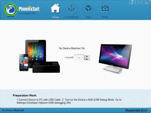
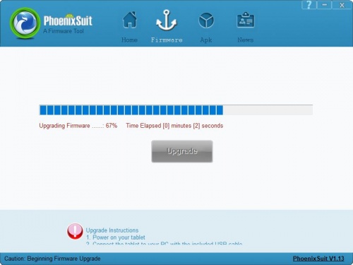
- Download the PhoenixSuit_V1.1.0.7z (Click here)and extract to a local folder (note: Windows only) and run one of the installers.
- Open the PhoenixSuit.exe.
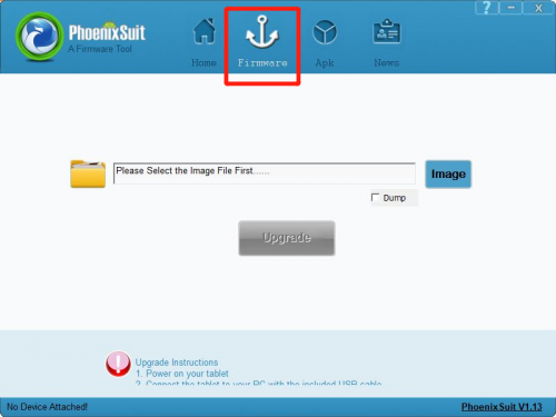
- Click the "firmware" button.
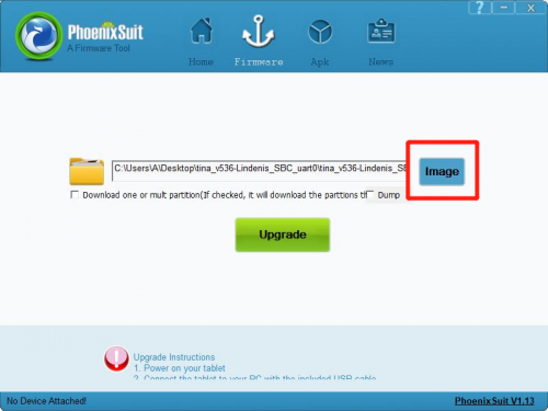
- Click the "image" button to select the image file.
- You can trigger the image downloading follow these step:
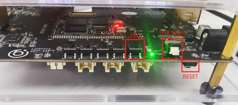
- 1) Connect the EVB to your PC via a USB cable, and you will see the green light. If you get a blue one, click the USB Select button to switch it.
- 2) Keep long press the "FEL" key, then press the "RESET" key to reset the board. Please just keep pressing the "FEL" key.
- Release the "FEL" key when you see below PC pop-up.
- If you want to keep the user data, please click "No". Click "Yes" will clean all datas in eMMC.Then will begin to download the image into eMMC.
- If you can not start to download, just plug-out the USB cable and try again.
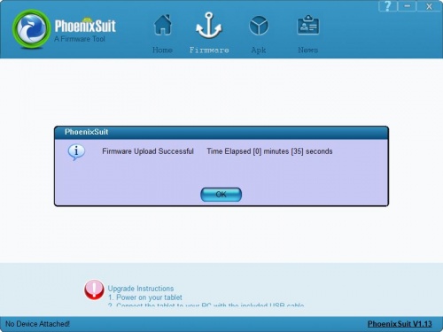
- Wait until it finish downloading.
OS
Overview
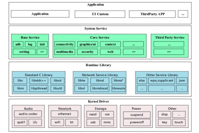
Tina Linux is an embedded OS developed by Allwinner based on openwrt-14.07 SDK. The OS architecture of Tina Linux is shown in the following diagram, from bottom to top, which are Kernel & Driver, Libraries, System Services and Applications.Applications
Applications layer is mainly to implement specific product functions and interaction logic. Developers can flexibly develop their own applications to achieve the various needs of customers.
System Services
System Services layer provides system infrastructure services, including system boot management, configuration management, storage and memory management, multimedia middleware, etc.
Libraries
Libraries layer contains support for various system base libraries and third-party open source libraries, which allows system developers and application developers to develop new system services and applications based on the APIs provided by this layer.
Kernel & Driver
Kernel & Driver layer is the standard implementation of the Linux Kernel. And the Tina SDK for V853 is based on Linux-4.9 kernel.
Reference Documents
Allwinner Official Reference Documents
If you cannot access the files, please send an e-mail to services@lindeni.com .
全志官方文档资料云盘下载-->提取码:v536
System Setup
Uart
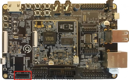
- By default, the ttyS3 is assigned to the Linux console. The UART transmit pin called "TX" and receive pin called "RX" are in the J12 pin group, whose label is DEBUG. And the bit rate is 115200 bps.See below red rectangle.
Camera
The camera supports the imx317 module as default. If you need to change to imx307, you can follow the steps below:
- 1.modify device/config/chips/v536/configs/Lindenis_SBC/sys_config.fex
find this:
sensor0_mname = "imx317_mipi"
change to:
sensor0_mname = "imx307_mipi"
- 2. make menuconfig selection
Allwinner --->
    eyesee-mpp --->
        -*-eyesee-mpp-middleware ............... eyesee-mpp-middleware for Tina Linux
            select sensor (use sensor imx307) --->
        () use sensor imx317
        (X) use sensor imx307
         () use sensor imx278
        () use sensor imx258
        () use sensor imx386
        () use sensor sc2232
- 3. do "make" and then flash the firmware.
ISP Tuning
Allwinner V536 ISP Tuning Tool | 国内提取码:c0u8
- Download the HawkviewTools-V3.0.2.7z and extract to a local folder (note: Windows only).
- Download the awTuningApp, push it into the board through ADB or SSH and then run it.
- Please refer to the documents in docs folder for usage.
- If you cannot access the files, please send an e-mail to services@lindeni.com .
Display
- Because of the limitation that there is one display engine module in V536, Lindenis-V536 SBC can not support dual-display.
- The default display device of the SDK and the prebuilt image is HDMI(1080p).
- If you have download the prebuilt image, and burn it into eMMC, you can switch the display device follow these steps:
Connect serial to control the board
- Firstly, you should connect the SBC debug UART to computer via a serial-USB cable so that you can send commands to the board through a PC serial software like Putty.
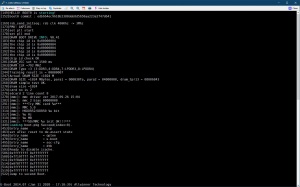
- After you connected successfully, you will see the log show on the PC serial software like this:
Enter U-boot command mode
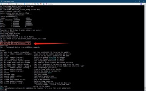
- Power on and press any keyboard key within 1s when you see the message below, then you can enter u-boot command mode.
- Under this mode, you can modify the kernel devices tree by FDT tools in u-boot.
Change display device configuration with FDT tool
- Input the follow command to switch display device between LCD and HDMI (1080p):
LCD:
fdt set disp screen0_output_type <0x01>;
fdt set disp screen0_output_mode <0x04>;
fdt save;
reset;
HDMI (1080p):
fdt set disp screen0_output_type <0x03>;
fdt set disp screen0_output_mode <0x0a>;
fdt save;
reset;
- You can also select different display device via configuration in sys_config.fex
;----------------------------------------------------------------------------------
;disp init configuration
;
;disp_mode             (0:screen0<screen0,fb0>)
;screenx_output_type   (0:none; 1:lcd; 2:tv; 3:hdmi;5:vdpo)
;screenx_output_mode   (used for hdmi output, 0:480i 1:576i 2:480p 3:576p 4:720p50)
;                      (5:720p60 6:1080i50 7:1080i60 8:1080p24 9:1080p50 10:1080p60)
;----------------------------------------------------------------------------------
[disp]
disp_init_enable         = 1
disp_mode                = 0

screen0_output_type      = 3
screen0_output_mode      = 10
TouchPanel
- After you connected the CTP panel to the board, insmod its driver like this:
insmod /lib/modules/4.9.118/gt9xx_ts.ko
- sys_config.fex should config as follow:
;----------------------------------------------------------------------------------
;capacitor tp configuration
;external int function
;wakeup output function
;notice ---    tp_int_port &  tp_io_port use the same port
;----------------------------------------------------------------------------------
[ctp]
ctp_used              = 1
ctp_name              = "gt911_1060"
ctp_twi_id            = 1
ctp_twi_addr          = 0x5d
ctp_screen_max_x      = 1280
ctp_screen_max_y      = 720
ctp_revert_x_flag     = 1
ctp_revert_y_flag     = 1
ctp_exchange_x_y_flag = 0

ctp_int_port          = port:PL06<6><default><default><default>
ctp_wakeup            = port:PL07<1><default><default><1>
Ethernet
- sys_config.fex should config as follow:
[gmac0]
gmac0_used         = 1  // 1: enable, 0 : disable
phy-mode           = "rgmii"
gmac_rxd3          = port:PE00<3><default><default><default>
gmac_rxd2          = port:PE01<3><default><default><default>
gmac_rxd1          = port:PE02<3><default><default><default>
gmac_rxd0          = port:PE03<3><default><default><default>
gmac_rxck          = port:PE04<3><default><default><default>
gmac_rxctl         = port:PE05<3><default><default><default>
gmac_clkin         = port:PE06<3><default><default><default>
gmac_txd3          = port:PE07<3><default><3><default>
gmac_txd2          = port:PE08<3><default><3><default>
gmac_txd1          = port:PE09<3><default><3><default>
gmac_txd0          = port:PE10<3><default><3><default>
gmac_txck          = port:PE11<3><default><3><default>
gmac_txctl         = port:PE12<3><default><3><default>
gmac_mdc           = port:PE13<3><default><3><default>
gmac_mdio          = port:PE14<3><default><3><default>
gmac_ephy25m       = port:PE15<3><default><default><default>
phy-rst            = port:PE21<1><default><default><0>
gmac-power0        = "vcc-ephy"
gmac-power1        = ""
gmac-power2        = ""
tx-delay           = 7
rx-delay           = 31
use_ephy25m        = 1
Wifi
- sys_config.fex should config as follow:
[wlan]
wlan_used           = 1
wlan_busnum         = 1
;wlan_usbnum        = 3
wlan_power          = "vcc33-wifi"
wlan_io_regulator   = "vcc-pg"
;wlan_en            = port:PG11<1><default><default><0>
wlan_regon          = port:PG11<1><default><default><0>
wlan_hostwake       = port:PL05<6><default><default><0>
- make sure CONFIG_BCMDHD is configured when make kernel_menuconfig
CONFIG_BCMDHD = m
- make sure PACKAGE_ap6255-firmware is configured when make menuconfig
PACKAGE_ap6255-firmware = y
- insmod driver as follow:
insmod /lib/modules/4.9.118/bcmdhd.ko
- Then you can use ifconfig and wpa_supplicant tools connect network
Bluetooth
- sys_config.fex should config as follow:
[bt_para]
bt_used             = 1
bt_power            = "vcc33-wifi"
bt_io_regulator     = "vcc-pg"
bt_rst_n            = port:PG10<1><default><default><0>
- You can take the follow shell cmd to start bt
echo 0 > /sys/class/rfkill/rfkill0/state
sleep 2
echo 1 > /sys/class/rfkill/rfkill0/state
sleep 2
brcm_patchram_plus  --tosleep=200000 --no2bytes --enable_hci --scopcm=0,2,0,0,0,0,0,0,0,0 \
                         --baudrate 115200 --patchram /lib/firmware/BCM4345C0.hcd  /dev/ttyS1 &
- When the bt device is started, you can use hciconfig tools to do someting you want
- (if hciconfig is not install, you should add it when make menuconfig)
Ethernet
- sys_config.fex should configured as follow:
[gmac0]
gmac0_used         = 1
phy-mode           = "rgmii"
gmac_rxd3          = port:PE00<3><default><default><default>
gmac_rxd2          = port:PE01<3><default><default><default>
gmac_rxd1          = port:PE02<3><default><default><default>
gmac_rxd0          = port:PE03<3><default><default><default>
gmac_rxck          = port:PE04<3><default><default><default>
gmac_rxctl         = port:PE05<3><default><default><default>
gmac_clkin         = port:PE06<3><default><default><default>
gmac_txd3          = port:PE07<3><default><3><default>
gmac_txd2          = port:PE08<3><default><3><default>
gmac_txd1          = port:PE09<3><default><3><default>
gmac_txd0          = port:PE10<3><default><3><default>
gmac_txck          = port:PE11<3><default><3><default>
gmac_txctl         = port:PE12<3><default><3><default>
gmac_mdc           = port:PE13<3><default><3><default>
gmac_mdio          = port:PE14<3><default><3><default>
gmac_ephy25m       = port:PE15<3><default><default><default>
phy-rst            = port:PE21<1><default><default><0>
gmac-power0        = "vcc-ephy"
gmac-power1        = ""
gmac-power2        = ""
tx-delay           = 7
rx-delay           = 31
use_ephy25m        = 1
- make sure CONFIG_SUNXI_GMAC is configured when make kernel_menuconfig
CONFIG_SUNXI_GMAC = y
Keypad
- The Keypad on the board is an GPADC keypad. The GPADC driver detect the different voltage of the keys and report the key value to user space via Linux standard Input Subsystem.
- Here is the parameters show in the sys_config.fex:
;----------------------------------------------------------------------------------
;resistance gpadc configuration
:gpadc_used :   Enable the GPADC
;channel_num:   Maxinum number of channels supported on the platform.
;channel_select:   channel enable setection. channel0:0x01  channel1:0x02 channel2:0x04 channel3:0x08
;channel_data_select:  channel data enable.  channel0:0x01  channel1:0x02 channel2:0x04 channel3:0x08.
;channel_compare_select:   compare function enable channel0:0x01  channel1:0x02 channel2:0x04 channel3:0x08.
;channel_cld_select:  compare function low data enable setection: channel0:0x01  channel1:0x02 channel2:0x04 channel3:0x08.
;channel_chd_select:  compare function hig data enable setection: channel0:0x01  channel1:0x02 channel2:0x04 channel3:0x08.
;----------------------------------------------------------------------------------
[gpadc]
gpadc_used                      = 1
channel_num                     = 1
channel_select                  = 0x01
channel_data_select             = 0
channel_compare_select          = 0x01
channel_cld_select              = 0x01
channel_chd_select              = 0x01
channel0_compare_lowdata        = 1700000
channel0_compare_higdata        = 1200000
key_cnt                         = 5
key0_vol                        = 116
key0_val                        = 115
key1_vol                        = 233
key1_val                        = 114
key2_vol                        = 357
key2_val                        = 139
key3_vol                        = 473
key3_val                        = 28
key4_vol                        = 586
key4_val                        = 102
Audio
audiocodec
- sys_config.fex should configured as follow:
[sndcodec]
sndcodec_used   = 0x1

[i2s]
i2s_used        = 0x1

[codec]
codec_used      = 0x1
lineoutvol      = 0x1f
maingain        = 0x4
headsetmicgain  = 0x4
adcagc_cfg      = 0x0
adcdrc_cfg      = 0x0
adchpf_cfg      = 0x0
dacdrc_cfg      = 0x0
dachpf_cfg      = 0x0
pa_ctl_level    = 0x1
pa_msleep_time  = 0xa0
gpio-spk        = port:PH10<1><1><default><default>
i2s
- sys_config.fex should configured as follow, and the param should configured accord your device need:
- if you i2s1 is used
[snddaudo0]
snddaudio0_used     = 1

[daudio0]
daudio0_used        = 1
daudio_master       = 4
audio_format        = 4
signal_inversion    = 1
slot_width_select   = 32
pcm_lrck_period     = 128
msb_lsb_first       = 0
sign_extend         = 0
frametype           = 0
mclk_div            = 1
tdm_config          = 0
tx_data_mode        = 0
rx_data_mode        = 0
- if you i2s2 is used
[snddaudo2]
snddaudio2_used     = 1

[daudio2]
daudio2_used        = 1
daudio_master       = 4
audio_format        = 1
signal_inversion    = 1
slot_width_select   = 32
pcm_lrck_period     = 32
msb_lsb_first       = 0
sign_extend         = 0
frametype           = 0
mclk_div            = 0
tdm_config          = 1
tx_data_mode        = 0
rx_data_mode        = 0
- make sure CONFIG_SND_SUNXI_SOC_SUNXI_DAUDIO configured when make kernel_menuconfig
CONFIG_SND_SUNXI_SOC_SUNXI_DAUDIO = y
Lindenis-V853 Hardware Tester
LindSDK Application Demo
The application demos powered by Lindenis.Click here to download the demos
