Lindenis V833
Contents
Key Features
Processor core
- Single-core ARM Cortex-A7 Processor
- ARMv7 ISA standard ARM instruction set
- Thumb-2 Technology
- Jazeller RCT
- NEON Advanced SIMD
- VFPv4 floating point
- 32KB L1 Instruction cache and 32KB L1 Data cache
- 128KB L2 cache
Video Encoding Performance
- H.264 BP/MP/HP, H.265 Main Profile encoding
- I/P/Dual P frame H.264/H.265 encoding
- MJPEG/JPEG baseline encoding
- Real-time multi-stream H.264/H.265 encoding capability:
- 5M@20fps + 1080p@20fps (or 1080p@60fps + VGA@60fps ) H.264
- 5M@30fps + 720p@30fps (or 1080p@90fps) H.265
- Maximum 8-megapixel resolution for H.264/H.265 encoding
- JPEG snapshot performance of 1080p@60fps independently
- CBR, VBR modes
- Output bit-rate ranging from 2kbit/s to 100Mbit/s.
- Maximum 16 ROIs without encoding for AI
- Encoding frame rate ranging from 1/16 fps to 60fps.
Video and Graphics Processing
- Support Electronic Image Stabilization Engine
- Supports Lens distortion correction, fisheye PTZ and calibration
- Picture rotation by 90°180°270°
- Support 2 Video channels, one up to 1080p@60fps, the other one up to 720p@60fps
- Support 1 UI channel, up to 1080p@60fps
- Blending of 2 Video channels and 1 UI channel
- Support SmartColor for excellent display experience
NPU Processing
- Maximum performance up to 0.4Tops
- Support Conv, Activation, Pooling, BN, LRN, FC/Inner Product
- Support Face detect, face recognition, human detection
Professional Image Effects
- Maximum performance is 2592 x1936@30fps
- Maximum resolution of is 2688 x 2688
- Adjustable 3A functions (AE, AWB and AF)
- Supports 2F WDR and Local Tone mapping,
- Supporting highlight suppression and backlight compensation, bad pixel correction, Lens shading correction
- Supports defect pixel correction, 2D/3D denoising.
- Supports image mirroring and flipping
- Provides ISP tuning tools for the PC
Various interfaces
- Wi-Fi : XR819
- BT1120 IN/OUT
- SPK, LINE-IN
- MIPI CSI, MIPI DSI, TP
- KEY, POWER_KEY, FEL
- Network: 10/100Mbps Ethernet
- USB: 1 x Micro USB, TF card
- Power Supply: 5V/2A micro USB, 5V/2A DC-IN, 3.7V Battery
Software Support
- Tina (base on linux-4.9)
- RTOS
Target Applications
- SDV
- Smart IPC
- Smart Camera
Accessories Step-by-Step Guides
Power Supply
LCD
Hardware Specification
Board Features
Video Out
- MIPI-DSI, 4 lanes, up to 1080P
- LCD interface
- BT1120 OUT
Video In
- 1 x MIPI-CSI - Camera interface, 4 lanes per channel
- BT1120 IN
Audio
- 3.5mm Line in
- SPK
- 1 x mic
Network
- 10/100/100 Ethernet
- WiFi 2.4G
Storage
- MicroSD Card bootable, support SDHC and SDXC, storage up to 256GB
Expansion Ports
- Flexible Pin Headers 2x13 pins Reserved:
- GPADC
- 5V, 1V8, 2V8 and DC Power Supply
- I2C x 1
- I2S x 1
- PWM x 1
Board Information
- Board Dimensions: 75mm x 68mm
- Input Power: 5V@2A micro USB connector, 3.7V Li-Ion battery connector
Hardware Documents
Datasheets
- V833 Datasheet
- V833 PINOUT V1.1
- PMIC AXP2101 Datasheet
- XR819 WIFI Datasheet
- Ethernet Transceiver Datasheet
- SPI NOR Flash MX25L12835FM2I-10G Datasheet
Schematic and Silk
- v833_Lindenis_SBC_V2_0_Schematic.pdf
- v833_Lindenis_SBC_V2_0_SILK_TOP.pdf
- v833_Lindenis_SBC_V2_0_SILK_BOTTOM.pdf
Support lists
- v833 SDRAM support list
- v833 eMMC support list
- v833 camera sensor support list
- v833 SPI NAND flash support list
- v833 SPI NOR flash support list
SDK
Lazy Start
Tina Linux
Tina Linux Overview
Features
- Linux Kernel 4.9 (official version)
- u-boot-2018
- ARM GCC based cross toolchain
- Integrated build system
Layout
├── build
├── config
├── Config.in
├── dl
├── lichee
├── logs
├── Makefile
├── package
├── prebuilt
├── rules.mk
├── scripts
├── softwinner
├── target
├── toolchain
└── tools
Download and Build
Prebuilt Image
For fast begin, you can download the prebuilt image here. Click me
国内开发者请在此下载提取码:v833
System requirements
Listed below are the recommended requirements for downloading and building the SDK:
- CPU: x86_64 or better family processor
- Memory: 8GB or higher
- Disk: 20GB free hard disk space, if you build it in a Virtual machine, I recommand you allocate a 30G virtual hard disk.
- The Whole SDK is about 15G.
- OS: Ubuntu 14.04 (tested) or higher
- Network: internet connection
Linux host setup
Ubuntu 14.04
HINT: later version should also work.
Install prerequisites
$ sudo apt-get update
$ sudo apt-get install build-essential libncurses5-dev zlib1g-dev gawk git git-core ccache gettext libssl-dev xsltproc gperf subversion
$ sudo dpkg --add-architecture i386
$ sudo apt-get update
$ sudo apt-get install lib32z1 lib32ncurses5 libc6:i386 libstdc++6:i386
Sudo without password
$ sudo visudo
Add this line at the end (change “tom” to your username):
tom ALL=(ALL) NOPASSWD: ALL
Ctrl-X to leave, save your changes, and you're done!
Downloading
The SDK is available on github. For Chinese developer, it is available on gitee too.
由于国内从Github上下载速度较慢,建议从Gitee上下载 --> Another way to get the SDK from Gitee
We use Repo manage Git repositories. Clone Repo from android Git repositories or other mirrors and install it.
Becase there are some big files in the SDK, please run the following command before you start the downloading.
$ git config --global http.postBuffer 524288000
Then run this to check:
$ git config --list
For Lindenis V833 SBC, download the SDK on Github via:
$ mkdir v833-lindenis
$ cd v833-lindenis
$ repo init -u https://github.com/lindenis-org/manifest.git -b v833 -m v833-lindenis.xml
$ repo sync
The Download time depends on your network connection speed. After finish the download, you should get below directories and files:
build config Config.in device lichee Makefile package prebuilt rules.mk scripts softwinner target toolchain tools
Start a branch for local workspace:
$ repo start v833-lindenis --all
Building
1.setup env
- For Lindenis V833 SBC:
$ source build/envsetup.sh
$ lunch
Then you will see the follwing menu, and enter the number to select the target case, and enter:
You're building on Linux

Lunch menu... pick a combo:
     1. v833_lindenis-tina

Which would you like?: 1
2.build source
- Build kernel and rootfs
If you are the first time to download the SDK and have not built the SDK before, run the below two commands, then exit and save the configuration at first.
$ make menuconfig
$ make kernel_menuconfig
Then make it and wait ...
$ make -j8 V=s
3.build image
$ pack
Installation
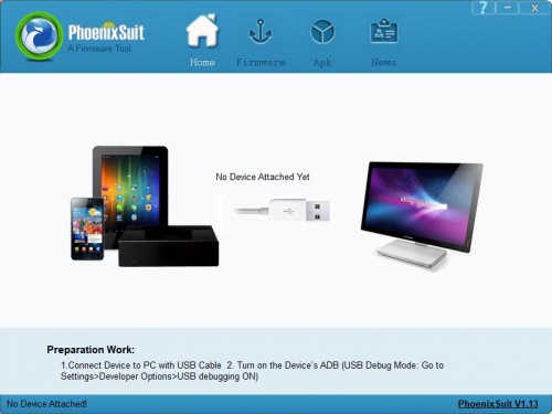
- Download the PhoenixSuit_V1.1.0.7z (Click here)and extract to a local folder (note: Windows only) and run one of the installers.
- Open the PhoenixSuit.exe.
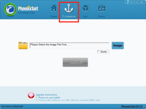
- Click the "firmware" button.
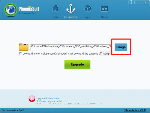
- Click the "image" button to select the image file.
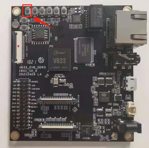
- Now the PC tool is ready. Just keep pressing the "fel" key on the SBC.
Tina Linux OS
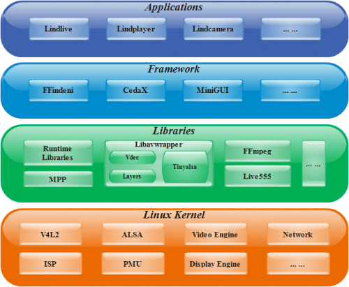
Lindenis Video OS is the recommended operating system for normal use on Lindenis V833 series boards. Lindenis Video OS is maintained by Lindenis Tech. Ltd.. The SDK is hosted on GitHub and Gitee.
Applications
- Lindlive: a low-laternce A/V streaming application powered by Lindenis.
- Lindplayer: a meida player application powered Lindenis.
- Lindcamera: a camera application (supported preview, snapshot and recording) powered by Lindenis.
- ... ...
Framewrok
- FFindeni: a multimedia framework specialized for low-latency A/V processing built by Lindenis.
- CedarX: a Allwinner official multimedia decoding framework.
- MiniGUI: a tiny and efficiency open source GUI framework.
- ... ...
Libraries
- Runtime Libraries: the system basic libraries like libc and so on.
- Libavwrapper: a Lindenis-built library abstracted the hardware operation of the A/V processing.
- FFmpeg: an open source software library for recording, converting and streaming audio and video.
- Live555: an open source software library for streaming audio and video.
- ... ...
Linux Kernel
- Official version: 4.9
Reference Documents
System Setup
Uart
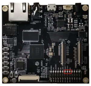
- By default, the ttyS3 is assigned to the Linux console. The UART transmit pin called "TX" and receive pin called "RX" are in the pin group. And the bit rate is 115200 bps.See below red rectangle.
Camera
- board.dts should config as follow:
sensor0:sensor@0 {
device_type = "sensor0";
sensor0_mname = "imx307_mipi";
sensor0_twi_cci_id = <1>;
sensor0_twi_addr = <0x34>;
sensor0_mclk_id = <0>;
sensor0_pos = "rear";
sensor0_isp_used = <1>;
sensor0_fmt = <1>;
sensor0_stby_mode = <0>;
sensor0_vflip = <0>;
sensor0_hflip = <0>;
sensor0_iovdd-supply = <®_aldo2>;
sensor0_iovdd_vol = <1800000>;
sensor0_avdd-supply = <>;
sensor0_avdd_vol = <2800000>;
sensor0_dvdd-supply = <®_dldo2>;
sensor0_dvdd_vol = <1200000>;
sensor0_power_en = <>;
sensor0_reset = <&pio PI 3 1 0 1 0>;
sensor0_pwdn = <&pio PI 4 1 0 1 0>;
status = "okay";
};
Display
The defalt display is LCD.
- board.dts should config as follow:
disp: disp@01000000 {
disp_init_enable = <1>;
disp_mode = <0>;
screen0_output_type = <1>;
screen0_output_mode = <4>;
disp_rotation_used = <1>;
degree0 = <1>;
fb0_format = <0>;
fb0_width = <1280>;
fb0_height = <720>;
lcd0_backlight = <50>;
lcd0_bright = <50>;
lcd0_contrast = <50>;
lcd0_saturation = <57>;
lcd0_hue = <50>;
dldo1-supply = <®_dldo1>;
bldo1-supply = <®_bldo1>;
dcdc1-supply = <®_dcdc1>;
aldo3-supply = <®_aldo3>;
};
lcd0: lcd0@01c0c000 {
lcd_used = <1>;
lcd_driver_name = "lx50hdi4002";
lcd_backlight = <150>;
lcd_if = <4>;
lcd_x = <720>;
lcd_y = <1280>;
lcd_width = <65>;
lcd_height = <118>;
lcd_dclk_freq = <56>;
lcd_pwm_used = <1>;
lcd_pwm_ch = <9>;
lcd_pwm_freq = <50000>;
lcd_pwm_pol = <1>;
lcd_pwm_max_limit = <255>;
lcd_hbp = <20>;
lcd_ht = <768>;
lcd_hspw = <8>;
lcd_vbp = <16>;
lcd_vt = <1314>;
lcd_vspw = <2>;
lcd_dsi_if = <0>;
lcd_dsi_lane = <4>;
lcd_dsi_format = <0>;
lcd_dsi_te = <0>;
lcd_dsi_eotp = <0>;
lcd_frm = <0>;
lcd_io_phase = <0x0000>;
lcd_hv_clk_phase = <0>;
lcd_hv_sync_polarity= <0>;
lcd_gamma_en = <0>;
lcd_bright_curve_en = <0>;
lcd_cmap_en = <0>;
lcdgamma4iep = <22>;
lcd_power = "dcdc1";
lcd_pin_power = "bldo1";
lcd_gpio_0 = <&pio PD 9 1 0 3 1>;
};
TouchPanel
If you want to use the CTP, please insmod its driver manually.
# insmod /lib/modules/4.9.118/gt9xx_ts.ko
- board.dts should config as follow:
ctp:ctp {
     device_type = "ctp";
     ctp_name = "gt911_1060";
     ctp_twi_id = <0x0>;
     ctp_twi_addr = <0x5d>;
     ctp_screen_max_x = <1280>;
     ctp_screen_max_y = <720>;
     ctp_revert_x_flag = <1>;
     ctp_revert_y_flag = <1>;
     ctp_exchange_x_y_flag = <0>;
     ctp_int_port = <&pio PC 10 6 0 0 1>;
     ctp_wakeup = <&pio PC 11 1 0 3 1>;

     status = "okay";
 };
Ethernet
- board.dts should config as follow:
gmac0: eth@05020000 {
        compatible = "allwinner,sunxi-gmac";
        pinctrl-names = "default", "sleep";
        pinctrl-0 = <&gmac_pins_a &gmac_pins_b &gmac_pins_c &gmac_pins_d>;
        pinctrl-1 = <&gmac_pins_e>;
        phy-mode = "rmii";
        use_ephy25m = <1>;
        tx-delay = <7>;
        rx-delay = <31>;
        phy-rst = <&pio PH 4 1 1 1 0>;
        gmac-power0;
        gmac-power1;
        gmac-power2;
        status = "okay";
};
Wifi
board.dts should config as follow:
wlan:wlan {
compatible = "allwinner,sunxi-wlan";
clocks = <&clk_losc_out>;
wlan_busnum = <1>;
wlan_usbnum = <3>;
wakeup_source = <0>;
wlan_power-supply = <®_dcdc1>;
io_regulator-supply = <®_dcdc5>;
wlan_power_vol = <3300000>;
io_regulator_vol = <3300000>;
/*wlan_en;*/
wlan_regon = <&pio PG 7 1 0 1 0>;
wlan_hostwake = <&pio PG 6 0 0 1 0>;
status = "okay";
};
Keypad
Audio
audiocodec
- board.dts should config as follow:
codec:codec@0x05096000 {
        pa_level = <0x1>;
        main_gain = <0x17>;
        adcdrc_cfg = <0x00>;
        adchpf_cfg = <0x01>;
        dacdrc_cfg = <0x00>;
        dachpf_cfg = <0x00>;
        digital_vol = <0x00>;
        lineout_vol = <0x1a>;
        pa_msleep_time = <0xa0>;
        gpio-spk = <&pio PH 3 1 1 1 1>;
        status = "okay";
};
i2s
- board.dts should config as follow:
snddaudio0:sound@1 {
        audio_format = <0x01>;
        daudio_master = <0x04>;
        signal_inversion = <0x01>;
        sunxi,snddaudio-codec = "ac108.1-003b";
        sunxi,snddaudio-codec-dai = "ac108-pcm0";
        status = "disabled";
};
Lindenis Application Demo
Lindlive
lindlive is a high performance low latency live streaming library. lindlive integrate some useful function modules, such as audio/video capture, encoding and streaming protocol. So developers can easily implement a live streaming server based on lindenis board.
There are two samples app using lindlive, one is sample_mppsrc_2_livesink and the other is sample_mppsrc_2_ffsink. The sample source code is located in SDK.
!!! It is strongly recommended to use lindplayer with '-live' as the client of the lindlive. It will be lower latency.
usage:
   sample_mppsrc_2_livesink -i [ip] -p [port] -n [name]
       -i [ip] is the ip address of the server. If it is not set, the 'ip' default is local ethernet or wifi ip address.
       -p [port] is the port of the server. If it is not set, the 'port' default is rtsp port 8554.
       -n [name] is the name of live streaming. If it is not set, the 'name' default is 'live'.
       All of the arguments are optional.
   If sample_mppsrc_2_livesink is correctly running, the server url is 'rtsp://[ip]:[port]/[name]'
   Then it can be played in an player with the url 'rtsp://[ip]:[port]/[name]'.
   sample_mppsrc_2_ffsink -t [type] -u [url]
       -t [type]: the muxer type, can be 'mpegts/mp4/rtp/rtp_mpegts/rtsp/rtmp'
       -u [url] : sink to url, like: '/tmp/out.mp4' or 'rtp://192.168.1.100:12345'
   Example 1: sink as a live streaming.
       sample_mppsrc_2_ffsink -t rtp_mpegts -u rtp://192.168.3.118:12345
       sample_mppsrc_2_ffsink -t rtp -u rtp://192.168.3.118:12342/test
       Then it can be played in an player with the url 'rtsp://[ip]:[port]/[name]'.
   Example 2: save as a local file.
       sample_mppsrc_2_ffsink -t mp4 -u /tmp/out.mp4
       sample_mppsrc_2_ffsink -t mpegts -u /tmp/out.ts
